K = 10
Products
Introduction
Conductivity probes are used with a conductivity meter to measure the conductance of a solution. They can also be used with a TDS meter to measure total dissolved solids. There is an array of conductivity cells available with different cell materials, cell constants, body materials, connectors, and ATC elements. It is necessary to choose a probe with a proper cell constant, temperature compensator, and connector to match the meter being used and the range to be measured. Glass body probes with platinum cells are suitable for almost all applications, even solutions with organic solvents. Epoxy body probes with platinum cells offer not only a wide measuring range capability, but also epoxy body durability. Epoxy body probes with carbon cells are designed for general purpose measurements. Their measuring range is not as wide as platinum cells; however, their durability can meet the challenge of tough applications, especially rough field use. Use a cell constant of K=1 cm for full range measurements, a cell constant of K=10 cm for the high range, and a cell constant K=0.1 cm for the low range.
Electrode Preparation & Meter Calibration
Before using a conductivity probe, soak the probe in distilled water for about 30 minutes. Make sure the measuring cells are clean. Connect the probe to a conductivity/TDS meter. Dip the probe in a 0.1 M KCl solution or other standard with known value. The cell portion of the probe must be totally immersed in the known solution. Stir the probe to get rid of any air bubbles trapped within the cell chamber. No air bubbles can be present in the cell chamber. If a 0.1 M KCl solution is used to calibrate the meter, adjust the meter reading according to the attached chart at the corresponding temperature. If other standards are used to calibrate the meter, refer to the standard value printed on the bottle. To use, rinse the probe cell portion with distilled water, put the probe in an unknown solution, and then shake the probe well to get rid of air bubbles within the cell chamber. The meter will display the correct conductance of the solution.
Maintenance
Do not touch the probe cell surface with any hard object. If the probe cell surface is contaminated, soak the probe cell portion in light detergent and mild acid for about 15 minutes respectively. Rinse the probe well with distilled water. [NOTE] Most platinum cells are electroplated with a layer of black platinum for better performance. Re-electroplate the platinum cells when the probe can no longer perform proper calibration.
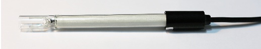
Cell Constant 10
MODEL : NC-10G
In theory, a conductivity measuring cell is formed by two 1-cm square surfaces spaced 1-cm apart. Cells of different physical configuration are characterized by their cell constant, C. This cell constant (C) is a function of the electrode areas, the distance between the electrodes and the electrical field pattern between the electrodes. The theoretical cell just described has a cell constant of C = 1.0. Often, for considerations having to do with sample volume or space, a cell’s physical configuration is designed differently. Cells with constants of 1.0 cm-1 or greater normally have small, widely spaced electrodes. Cells with constants of C = 0. 1 or less normally have large closely spaced electrodes. Since C (cell constant) is a “factor” that reflects a particular cell’s physical configuration, it must be multiplied by the observed conductance to obtain the actual conductivity reading.
For example, for an observed conductance reading of 1,413 µS using a cell with K = 0.01, the conductivity value is 1,413 × 0.01 = 14.13 µS/cm.
Conductivity sensors are characterized by a cell constant – a geometry dependent parameter that relates the conductance (or resistance) measured by the cell to the solution’s conductivity (or bulk resistivity), as,
ρ = C · G ———- (1)
where,
G is the cell conductance, in Siemens (or mhos),
C is the cell constant, in cm-1, and,
ρ is the solution conductivity, as S/cm or µS-cm-1.
Conductivity sensors are fabricated using a variety of electrode geometries. In the past the use of parallel planar electrodes made determination of the sensor’s cell constant an easy computation. In that case the cell constant is given by the ratio of electrode separation to electrode area:
C = S/A ———- (2)
This equation holds well for large electrode areas and small separation. In that case, most of the electrode current flows directly between the electrodes, and the small current in the fringing field can be neglected.
But now it’s possible to manufacture miniature electrolyte conductivity sensors using microfabrication techniques. These sensors usually use planar-interdigitated electrodes, around and between which the solution conductance is measured. While conductivity cells using these electrodes may be calibrated using standard solutions, diagnosis and verification of cell function still requires an a priori estimation of their theoretical cell constant. But that’s difficult because in this case all the electrode current flows through the fringing field.