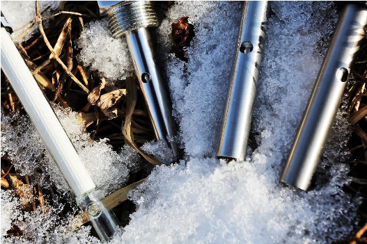
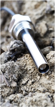
Conductivity sensor
Products
There are two(Contacting and Toroidal)basic sensor styles used for measuring Conductivity. Toroidal conductivity is a technique for measuring the concentration of electrolytes in solution and utilizes a probe consisting of two toroids in close proximity, both of which are immersed in the solution.
In special cases, the toroids may be mounted externally on insulated pipes carrying the solution. One toroid radiates an alternating electric field in the audiofrequency range and the other acts as a receiver to pick up the small current induced by the ions moving in a conducting loop of solution. Coatings which would foul contacting electrodes, such as suspensions, precipitates or oil, have little or no effect. Applications are chiefly to continuous measurement in the chemical processing industries, including pulp and paper, mining and heavy chemical production.
In theory, a conductivity measuring cell is formed by two 1-cm square surfaces spaced 1-cm apart. Cells of different physical configuration are characterized by their cell constant, C. This cell constant (C) is a function of the electrode areas, the distance between the electrodes and the electrical field pattern between the electrodes. The theoretical cell just described has a cell constant of C = 1.0. Often, for considerations having to do with sample volume or space, a cell’s physical configuration is designed differently. Cells with constants of 1.0 cm-1 or greater normally have small, widely spaced electrodes. Cells with constants of C = 0. 1 or less normally have large closely spaced electrodes. Since C (cell constant) is a “factor” that reflects a particular cell’s physical configuration, it must be multiplied by the observed conductance to obtain the actual conductivity reading.
Conductivity sensors are fabricated using a variety of electrode geometries. In the past the use of parallel planar electrodes made determination of the sensor’s cell constant an easy computation. In that case the cell constant is given by the ratio of electrode separation to electrode area : C = S/A
This equation holds well for large electrode areas and small separation. In that case, most of the electrode current flows directly between the electrodes, and the small current in the fringing field can be neglected.
But now it’s possible to manufacture miniature electrolyte conductivity sensors using microfabrication techniques. These sensors usually use planar-interdigitated electrodes, around and between which the solution conductance is measured. While conductivity cells using these electrodes may be calibrated using standard solutions, diagnosis and verification of cell function still requires an a priori estimation of their theoretical cell constant. But that’s difficult because in this case all the electrode current flows through the fringing field.
Units of Measurement
The basic unit of conductance is the siemen (S), formerly called the mho.
Although we specify conductivity ranges for our products in µS or mS, due to space limitations these ranges should be understood to reflect specific conductivity in µS/cm or mS/cm, respectively.
1 µS/cm = 0.001 mS/cm = 0.000001 S/cm = 1 µmho/cm
The following table shows optimum conductivity ranges for cells of three different constants:
| Cell Constant(C) | Optimum Conductivity Range(µS/cm) |
|---|---|
| 0.01 | 0.05~20 |
| 0.1 | 0.5 to 400 |
| 1.0 | 10 to 2000 |
| 10.0 | 1000 to 200,000 |
The conductivity of some common solutions is shown in the table below.
| Solution | Conductivity |
|---|---|
| Pure water | 0.055 µS/cm |
| Power plant boiler water | 1.0 µS/cm |
| Good city water | 50 µS/cm |
| Ocean water | 53 mS/cm |
| 31.0% HNO3 | 865 mS/cm |